
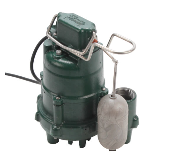
Groundwater doesn’t care about calendars. It moves in during heavy rain, snowmelt, spring thaw, and high water table seasons. A properly installed sump pump is the first and last line of defense against a flooded basement, and the difference between a dry foundation and a water damage claim often comes down to what happened during installation. Specifically, whether someone cut corners on pit prep, skipped the check valve, or used a cord not rated for the load. This guide covers every phase of a new sump pump installation from pit preparation through commissioning, the way an experienced plumber would approach the job.
Before the Work Starts: Code and Permit Requirements
All sump pump installations must comply with the National Electrical Code (NEC) and applicable local and state plumbing codes. Most jurisdictions require the discharge line to terminate to daylight or a storm drain, not to a sanitary sewer. Some require air gaps or backflow protection at the discharge outlet. Check local requirements before digging. The Zoeller installation instructions are explicit: all installations must comply with applicable electrical and plumbing codes, including but not limited to the NEC and local, regional, and state plumbing codes.
The circuit serving the pump must be separately protected and properly grounded per NEC requirements. Many inspectors require a dedicated 15- or 20-amp GFCI-protected circuit for sump pump installations in wet basement locations. Confirm with the authority having jurisdiction before rough-in.
Tools and Materials
Arriving with the wrong materials adds hours to an installation. Here’s what a complete install requires:
| Item | Notes |
| Submersible sump pump (1/3 or 1/2 HP) | Match HP to calculated flow and head requirements |
| Sump basin / liner (18″ diameter minimum) | Perforated basin allows groundwater entry |
| 1-1/2″ Schedule 40 PVC discharge pipe | Never use pipe smaller than pump discharge port |
| Inline check valve (1-1/2″ x 1-1/2″) | Prevents backflow into pit after pump shuts off |
| Union fitting | Required for future serviceability; install near pump discharge |
| PVC primer and solvent cement | Use primer on all cemented joints |
| 3/16″ drill bit (weep hole) | Prevents air lock between pump and check valve |
| Gravel or crushed stone | Drainage bed at pit base; 4″ to 6″ depth |
| Basin lid | Reduces odors, debris entry, and humidity; some codes require it |
| GFCI outlet or GFCI circuit breaker | Required by NEC for damp/wet locations |
| Wet/dry vacuum | Pit prep and commissioning test water removal |
| Tape measure, level, zip ties | Confirming pump sits flat; securing power cord |
Pump Selection: Submersible vs. Pedestal
Most new residential installations use a submersible pump. The entire unit sits below the water line inside the basin. Submersible models run cooler, operate more quietly, and work in tight pit diameters. Pedestal pumps mount the motor above the basin on a stand, with only the base and impeller submerged. They’re appropriate for extremely narrow pits where a submersible float won’t have clearance to swing.
| Feature | Submersible | Pedestal |
| Motor location | Submerged in pit | Above pit, on riser |
| Noise level | Lower (water absorbs vibration) | Higher (motor exposed) |
| Pit size required | 18″ diameter minimum (float clearance) | Can fit narrower pits |
| Typical HP range | 1/3 HP to 1 HP | 1/3 HP to 1/2 HP |
| Service access | Must lift pump from pit | Motor accessible above basin |
For most basement installs, a 1/3 HP submersible handles flow rates up to 35 to 43 GPM at 5 feet of head. Higher groundwater inflow, deeper pits, or long horizontal discharge runs require a 1/2 HP model. Always confirm against the pump’s published performance curve, not just the horsepower label. Head pressure drops flow significantly.
Browse the full lineup at SupplyHouse, including cast-iron submersible models, pedestal options, and combination primary-plus-backup systems:
Sump Pumps: https://www.supplyhouse.com/Sump-Pumps-1424000
Backup Sump Pumps: https://www.supplyhouse.com/Backup-Sump-Pumps-35210000
Step-by-Step Installation
- Locate or excavate the pit. The pit should be at the lowest point of the basement floor. For new construction, the pit is typically poured in place or formed before the slab. For retrofit installs, cut a hole slightly larger than the basin diameter with a concrete saw or jackhammer. Minimum recommended pit diameter is 18 inches to allow adequate float clearance. Excavate to a depth at least 6 inches deeper than the basin to accommodate the drainage bed.
- Install the drainage bed. Pour 4 to 6 inches of clean gravel or crushed stone into the pit base before setting the basin. This improves drainage into the liner and prevents the basin from settling unevenly.
- Set and level the basin. Drop the basin into the pit. Confirm it sits level in both directions with a torpedo level. A tilted basin causes float interference and uneven cycling. Backfill around the outside of the liner with gravel. Some installers use concrete to collar the top edge flush with the slab for a finished appearance.
- Set the pump flat in the basin. Place the submersible pump on the basin floor with the float arm oriented so it can swing freely without contacting the basin wall. Per Zoeller’s installation instructions, the pit should be 18 inches or larger in diameter to allow proper float travel. Confirm there’s clearance on all sides before attaching discharge piping.
- Attach the discharge pipe and union. Thread or push-fit a short nipple into the pump’s 1-1/2″ NPT discharge port. From there, cement a union fitting, then run Schedule 40 PVC discharge pipe upward. The union is not optional; it’s the only way to pull the pump for service without cutting pipe. Install it within 18 inches of the pump discharge.
- Drill the weep hole. Drill a 3/16-inch hole in the discharge pipe between the pump outlet and the check valve. This prevents air lock, which occurs when air trapped in the pipe blocks water flow and leaves the impeller spinning against nothing. The hole must be below the basin cover and cleaned periodically. A small stream of water will be visible from this hole during pump operation.
- Install the check valve. Mount a 1-1/2″ inline check valve in the discharge line above the pump and union, with the arrow on the valve body pointing up (direction of flow, away from the pump). The check valve stops discharged water from falling back into the pit when the pump shuts off. Without it, water re-enters the pit and triggers a new pump cycle immediately, causing short cycling that wears switches and motor windings prematurely. Browse check valves and pump accessories: Pump Accessories — SupplyHouse
- Run the discharge line to daylight. Continue the PVC discharge run to an exterior termination point, sloped continuously downhill at a minimum 1/4 inch per foot. The discharge must terminate at least 6 feet from the foundation and not direct water toward neighboring property or back toward any drainage inlet connected to the sanitary sewer. In cold climates, insulate exterior runs or install a freeze-guard fitting to prevent ice blockage. Verify local code requirements for discharge termination before final routing.
- Secure the cord to the discharge pipe. Per Zoeller installation instructions, securely tape or clamp the power cord to the discharge pipe and keep it clear of the float mechanism. A cord that hangs loose in the basin can wrap around the float arm, prevent the switch from operating, and cause the pump to run continuously or fail to start.
- Connect to a GFCI outlet. The pump requires a properly grounded, 3-prong GFCI outlet on a dedicated, separately protected circuit. Extension cords are explicitly prohibited by Zoeller installation instructions and create voltage drop that shortens motor life. If no code-compliant outlet exists within the cord reach, a licensed electrician must install one. For GFCI outlet requirements and options see:How to Check and Reset GFCI Outlets Before Storm Season — SupplyHouse Real Talk
- Commission with a water test. Before installing the basin lid, fill the pit with water using a garden hose. Watch the pump activate automatically when the float reaches the on-point, pump the basin down, and shut off cleanly at the off-point. Confirm the check valve is holding (water should not rush back into the pit audibly after shutdown). Walk the exterior discharge termination and confirm water exits where expected.
- Install the basin cover. Seat the lid over the basin once the system tests successfully. Some lids have notched openings for the discharge pipe and cord. Sealing the basin reduces radon entry in applicable regions, limits debris accumulation in the pit, and cuts humidity contribution to the basement air.
Check Valve Placement: Getting It Right
Check valve placement is one of the most common installation errors on pump jobs. Installing it too close to the pump causes water hammer when the valve snaps shut. Installing it too far allows a large column of water to fall back and hammer the pump impeller. Recommended practice from Zoeller documentation places the check valve in the vertical discharge line, as close to the pump as practical after the union, with the arrow facing in the direction of flow.
The weep hole must be between the pump discharge and the check valve, not above it. If it’s above the check valve, the hole serves no function. If it’s below, it will continuously drain the pipe between cycles, which is its intended purpose.
Most 1-1/2″ sump pump check valves are spring-loaded inline models with a clear body for visual inspection. The clear body is useful for confirming the valve is seating cleanly and not leaking. Available options including spring-loaded and swing-type models are listed under Pump Accessories at SupplyHouse.
Discharge Piping: Common Errors and How to Avoid Them
The discharge pipe is the part of a sump installation that fails silently. The pump works fine, but water returns to the foundation anyway.
- Undersized pipe: Never use a discharge pipe smaller than the pump’s discharge port (almost always 1-1/2″ for residential). Smaller pipe creates back pressure that reduces flow and can trap the pump near shut-off head.
- Insufficient slope: Horizontal runs that sag or run level hold standing water that can freeze in winter. Maintain continuous downward slope to the outlet.
- Discharge too close to foundation: Water terminating within 4 to 6 feet of the foundation re-enters the soil near the footing and cycles back to the pit. Move the outlet further out.
- Discharge into sanitary sewer: Most jurisdictions prohibit this outright. Stormwater in the sanitary system overloads treatment facilities. Always check code.
- No freeze protection on exterior runs: PVC exposed to outdoor temperatures in northern climates can freeze and burst or create an ice plug that blocks the line. Use a freeze-guard fitting or insulate the run.
Pit Sizing and Basin Selection
Pit diameter determines float clearance, pump cycling volume, and how much water is available as buffer during peak inflow events. A pit that’s too small causes the pump to short cycle at high speed, generating heat and shortening switch life. Zoeller’s installation instructions specify the pit be 18 inches or larger in diameter for proper float travel on standard residential models.
Basin depth affects how much water volume cycles per pump activation. A deeper basin with more volume between the float on and off points means longer run times, slower cycling, and less switch wear. For most residential basements, an 18-inch diameter by 22- to 30-inch deep basin provides a reasonable balance between space, cost, and performance.
Browse sump basins available at SupplyHouse: Pump Basins — SupplyHouse
Battery Backup Systems: Why They Matter
The storms that produce the most groundwater inflow are also the storms most likely to knock out power. A primary sump pump with no backup is a single point of failure in exactly the conditions where it’s needed most. Battery backup sump pump systems use a 12-volt deep-cycle marine battery to power a secondary pump in the event of power loss or primary pump failure.
A fully charged backup battery can support 5.5 to 7.5 hours of continuous pumping, depending on the system and battery capacity selected. That’s enough for most storm events. For areas with frequent extended outages or high groundwater, a combination system with both primary and battery backup mounted on a single discharge line offers the most complete protection.
Combination combo systems and battery backup systems at SupplyHouse: Backup Sump Pumps — SupplyHouse
Water-powered backup options, which require no battery and run directly off municipal water pressure, are covered separately on the blog:
Recommended Pumps at SupplyHouse
Two proven options for new residential installs:
| Model | HP / Voltage | Flow at 5 ft Head | Construction | Float Type |
| Zoeller M53 | 3/10 HP / 115V | 43 GPM | Cast iron | Tethered float |
| Liberty 257 | 1/3 HP / 115V | 43 GPM @ 10 ft | Cast iron | Vertical magnetic |
Zoeller M53 at SupplyHouse: Zoeller M53 Mighty-Mate Effluent/Sump Pump (SKU 53-0001) — SupplyHouse
Liberty Pumps 257 at SupplyHouse: Liberty Pumps 257 (SKU 257-LIBERTY) — SupplyHouse
FAQs
Q: What is the minimum pit diameter for a submersible sump pump?
A: Zoeller’s installation documentation specifies 18 inches as the minimum pit diameter to allow proper float travel on standard residential submersible models. Smaller pits cause the float to contact the basin wall, preventing the switch from reaching its full on or off position.
Q: Does the discharge pipe require a check valve?
A: Yes. Without a check valve, discharged water falls back into the pit after the pump shuts off, causing the float to rise again immediately and triggering another cycle. Short cycling is one of the fastest ways to burn out a pump motor and switch. Zoeller installation instructions explicitly require a check valve in the discharge line.
Q: Why is a union required in the discharge line?
A: A union allows the pump to be lifted out of the basin for service without cutting the discharge pipe. It’s a standard requirement in Zoeller installation documentation and good professional practice. Install it within 18 inches of the pump outlet.
Q: What is the weep hole for and where does it go?
A: A 3/16-inch hole drilled in the discharge pipe between the pump outlet and the check valve prevents air lock. Air trapped in the pipe can block water flow and cause the impeller to spin without moving water. The hole must be below the basin cover and cleaned periodically. A small stream of water exits the hole during pump operation.
Q: Can the pump share a circuit with other equipment?
A: No. Zoeller installation instructions require the pump to be connected to a separately protected and properly grounded circuit. Shared circuits with other loads introduce voltage fluctuation and risk nuisance tripping during peak demand.
Q: Can an extension cord be used with a sump pump?
A: Zoeller installation instructions explicitly prohibit using an extension cord with a sump pump. Extension cords introduce voltage drop, especially undersized cords on long runs, which shortens motor life and can prevent the pump from starting under load.
Q: What happens if the pump sits unlevel in the basin?
A: An unlevel pump causes the float arm to hang incorrectly, which can result in the switch failing to reach the on or off position. Vibration from operation also increases on a tilted pump. Always confirm the pump sits flat before connecting the discharge line.
Q: How far from the foundation should the discharge terminate?
A: At minimum 6 feet from the foundation to prevent discharged water from re-entering the soil near the footing. Local codes may require greater distances. The outlet must never direct water toward a neighboring property or back into any storm or sanitary drain connection.
Q: Does a new sump pump installation require a permit?
A: In most jurisdictions, yes. Plumbing and electrical permits are typically required for a new sump pump installation. Some municipalities also require an inspection before the basin is covered. Always check local requirements before beginning work.
Q: Should a battery backup system always be included?
A: For any basement with finished space, stored valuables, or mechanical equipment, a battery backup system is strong insurance. The storms most likely to produce the highest groundwater inflow are the same storms most likely to cause power outages. A backup pump adds minimal cost compared to the damage exposure of a primary pump failure during an outage.
Pumping Out the Problems
A sump pump installation done right is invisible for 10 years. Done wrong, it’s a callback within the first spring. The technical points that separate a clean install from a problem job are well-documented in manufacturer installation instructions: use a pit at least 18 inches in diameter, install a check valve and union in the discharge line, drill the weep hole between the pump and check valve, run to a dedicated GFCI circuit, and never use an extension cord. Walk the discharge line outside before calling the job done.
Browse submersible sump pumps, basins, check valves, and backup systems at SupplyHouse. For additional coverage on sizing and replacing sump pumps, see How to Size a Sump Pump and How to Test and Replace a Sump Pump on the SupplyHouse Real Talk blog.