
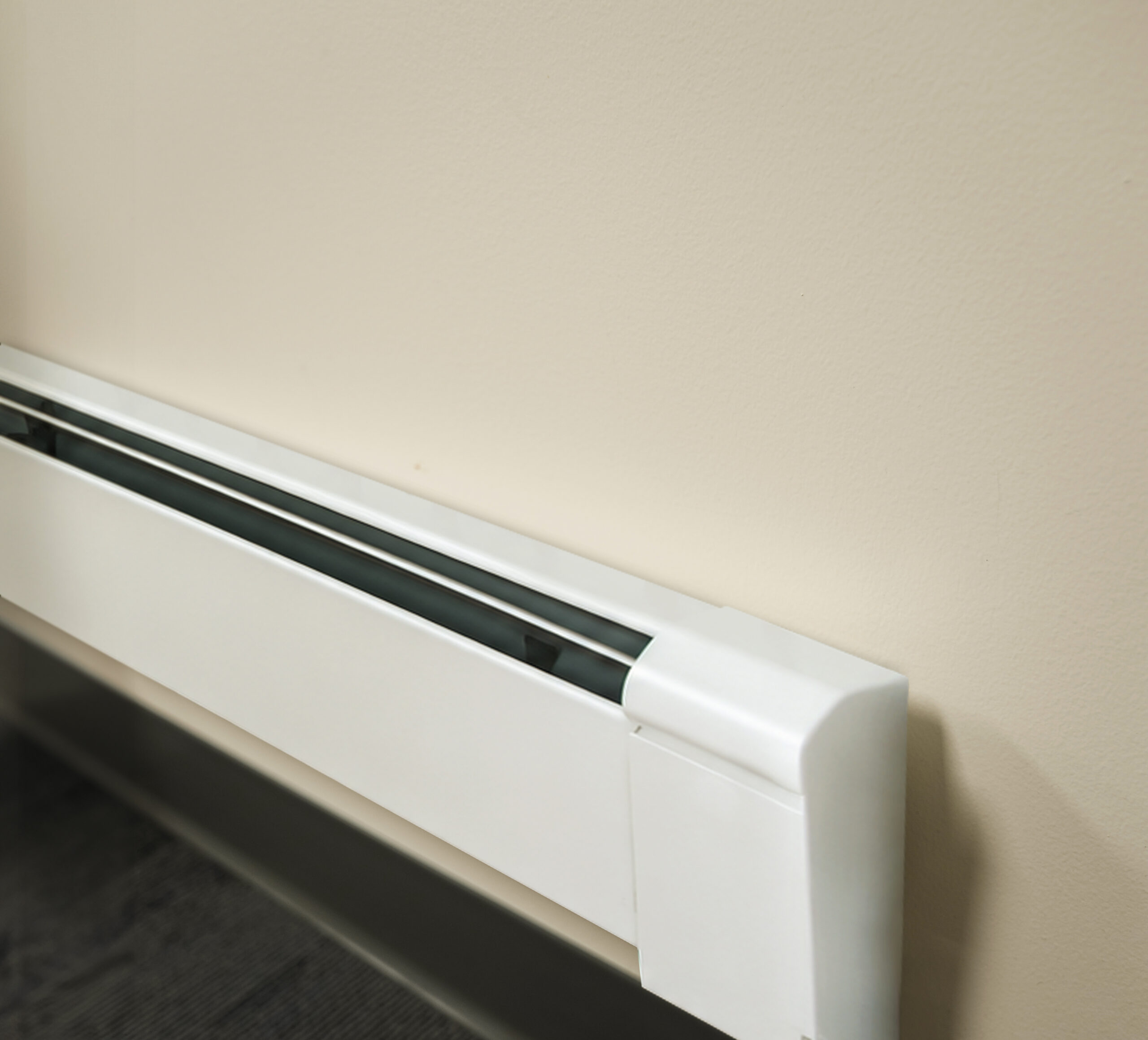
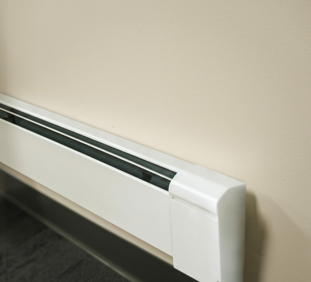
Baseboard is the most common hydronic heat emitter in residential construction for good reason. It’s reliable, inexpensive, simple to install, and delivers quiet, even convective heat from a low-profile wall enclosure. Getting the installation right comes down to three things: sizing the element correctly to the room’s heat load, laying out the piping so air can be vented properly, and connecting the enclosure so the fin section transfers heat efficiently. Get those right and the baseboard does its job for decades without complaint.
How Fin-Tube Baseboard Works
A fin-tube baseboard element is a length of copper tube with aluminum fins crimped at regular intervals. Hot water from the boiler flows through the tube. The fins multiply the heat transfer surface area, warming the air that convects naturally upward through the enclosure’s slots. The enclosure (back plate, end caps, and front cover) directs airflow across the fins and channels heated air upward into the room.
Standard residential baseboard elements use 3/4″ copper tube with aluminum fins spaced at approximately 55 fins per foot. Output varies by water temperature and flow rate. At 180 degrees F average water temperature (a common boiler setpoint for baseboard systems), most standard elements produce approximately 600 BTU per hour per linear foot.
Sizing the Baseboard Run
The room’s heat loss determines how many feet of baseboard are needed. A proper Manual J or room-by-room heat loss calculation is the right approach. For a quick field estimate, use the rule of thumb of 50 BTU/hr per square foot in a well-insulated room in a cold climate, less for moderate climates or well-insulated construction.
Example: a 200 square foot bedroom in a cold climate needs approximately 10,000 BTU/hr. At 600 BTU/hr per linear foot (180 degree average water temperature), that room needs approximately 17 feet of baseboard.
Key sizing notes:
- Output decreases significantly at lower water temperatures. At 150 degrees F average water temp, output drops to roughly 380 BTU/hr per foot. Size accordingly if the system runs at lower temperatures.
- Install baseboard under or adjacent to windows and exterior walls. Cold air falls from glazing and drafts from exterior walls are where heat loss concentrates.
- Series piping is standard for residential baseboard: water flows from the supply, through each baseboard element in sequence, and returns to the boiler. The last element in the loop receives cooler water than the first. For long loops, account for the temperature drop across the run.
Browse Slant/Fin baseboard heaters and enclosures and baseboard elements at SupplyHouse.
Tools and Materials
- Copper tubing (3/4″ for standard baseboard, sized to loop flow requirements)
- Baseboard element (fin-tube section) in required lengths
- Baseboard enclosure: back plate, end caps, front cover
- Sweat fittings or press fittings for copper connections
- Level, tape measure, drill, screws
- Pipe cutter, soldering torch and solder (or press tool if using press fittings)
- Pipe joint sealant only where the manufacturer calls for threaded fittings; many residential fin-tube elements use sweat-type element connections instead
Step-by-Step Baseboard Installation
Step 1: Mount the back plate. The back plate installs first and runs the full length of the baseboard run. Keep the bottom of the back plate 1 to 2 inches above the finished floor to allow airflow into the enclosure from below. Secure to wall studs or with appropriate wall anchors.
Step 2: Run the supply and return piping. Pipe enters and exits the enclosure through the end cap knockouts. The supply enters one end, the return exits the other. Slope the element and enclosure slightly upward toward the high point bleed valve (approximately 1/8 inch per foot) so air rises and can be purged rather than trapped.
Step 3: Install the baseboard element. The fin-tube element snaps or slides into the support brackets on the back plate. Connect the supply and return pipes to the element ends using sweat couplings. Ensure all joints are fully seated and soldered before enclosing.
Step 4: Install the end caps. Once piping and the element are in place, snap the end caps onto the back plate at both ends of the run. Punch out the appropriate knockouts for the supply and return piping to pass through cleanly.
Step 5: Pressure test before closing. Fill the zone with water, bring to operating pressure, and inspect all joints for leaks before installing the front cover. Leaks inside a closed enclosure cause water damage that is difficult to find and repair.
Step 6: Install the front cover. Snap the front cover onto the back plate and end caps to complete the enclosure. Keep the cover accessible for future bleeding or element replacement.
Step 7: Bleed the zone. After filling and pressurizing the system, open the bleed valve at the high point of the new run and allow air to purge until water flows steadily.
Common Installation Mistakes
| Mistake | Result | Prevention |
| Baseboard installed level with no return slope | Air traps in element, reduced heat output or no heat | Pitch return pipe slightly downward toward boiler |
| Element installed too close to floor | Insufficient airflow into enclosure, reduced convection | Maintain 1 to 2 inch clearance below enclosure bottom |
| Front cover installed before pressure test | Hidden leak causes water damage before discovery | Always pressure test with cover off |
| Element run too short for heat loss | Room never reaches setpoint temperature | Size to room heat loss, not available wall space |
| Pipe connections not fully sweat | Slow leak at element connections weeps inside enclosure | Full solder penetration on all joints; test before closing |
Adding Baseboard to an Existing System
Adding a new baseboard element to an existing series loop requires cutting into the existing pipe, adding tees, and routing the supply and return to the new element. Work through this checklist:
- Confirm the existing circulator has enough head to drive the added length. A longer loop increases flow resistance.
- On a series loop, the new element adds to the loop’s total footage. Verify the last element in the loop still receives adequate flow.
- Install isolation valves on the new branch where the piping arrangement allows and where they make service practical
- Bleed the new section after filling.
Adding a fully independent zone with its own circulator and zone valve avoids all flow balance issues and gives independent temperature control. For more than a small addition, a new zone is often the right approach.
Related: How to Design a Hydronic Heating System for zoning and piping design reference.
Frequently Asked Questions
How long can a single baseboard series loop be?
Most residential circulator pumps handle loops up to 200 to 250 feet of baseboard without flow problems. Longer loops require larger circulators or a primary-secondary piping arrangement. The practical limit is also heat loss: a long loop’s last emitters receive cooler water and produce less heat.
Can baseboard be installed on interior walls?
Yes, but it’s less effective at countering heat loss there. Baseboard works best under windows and along exterior walls where cold surfaces and drafts create the bulk of the room’s heat loss. Interior wall installations can supplement, but they shouldn’t be the primary emitter location.
What water temperature does baseboard need?
Standard fin-tube baseboard is designed for high-temperature operation, typically 160 to 200 degrees F average water temperature. At lower temperatures (as seen in radiant or condensing boiler systems), output drops significantly. Baseboard sized for 180 degrees F will underperform on a system running at 140 degrees F unless the element footage is increased to compensate.
Can I mix baseboard and radiant floor heat on the same boiler?
Yes, with a mixing valve or injection pump to supply the radiant zones at lower temperature while the baseboard zones receive boiler-temperature water. Running radiant floors at baseboard temperatures (180 degrees F) overheats the floor and damages flooring materials. Mixing controls are required.
How do I stop baseboard from making ticking noises?
Thermal expansion and contraction of the copper tube inside the enclosure causes ticking as the system heats up and cools down. Ensure the element is not pinched or constrained by a too-tight end cap or by pipe clamps that don’t allow movement. Adequate clearance between the element and the enclosure allows free expansion.
What is the right fin spacing for baseboard elements?
Fin spacing varies by manufacturer and product line. For example, Slant/Fin Fine/Line 30 uses 55 fins per linear foot. Match the installed element to the manufacturer’s published output table at the intended water temperature. Slant/Fin’s catalog sheet publishes 55 fins per foot for the E-75 element..
Bringing the Heat
Fin-tube baseboard is one of the most forgiving systems to install correctly when the sizing is right and the piping avoids air traps. It’s also one of the most common sources of callbacks when the element run is short-changed on length or the pipe connections weep inside a sealed enclosure. Size the baseboard to the room, pitch the return, test before closing the cover, and bleed the air out. That’s the whole procedure.