
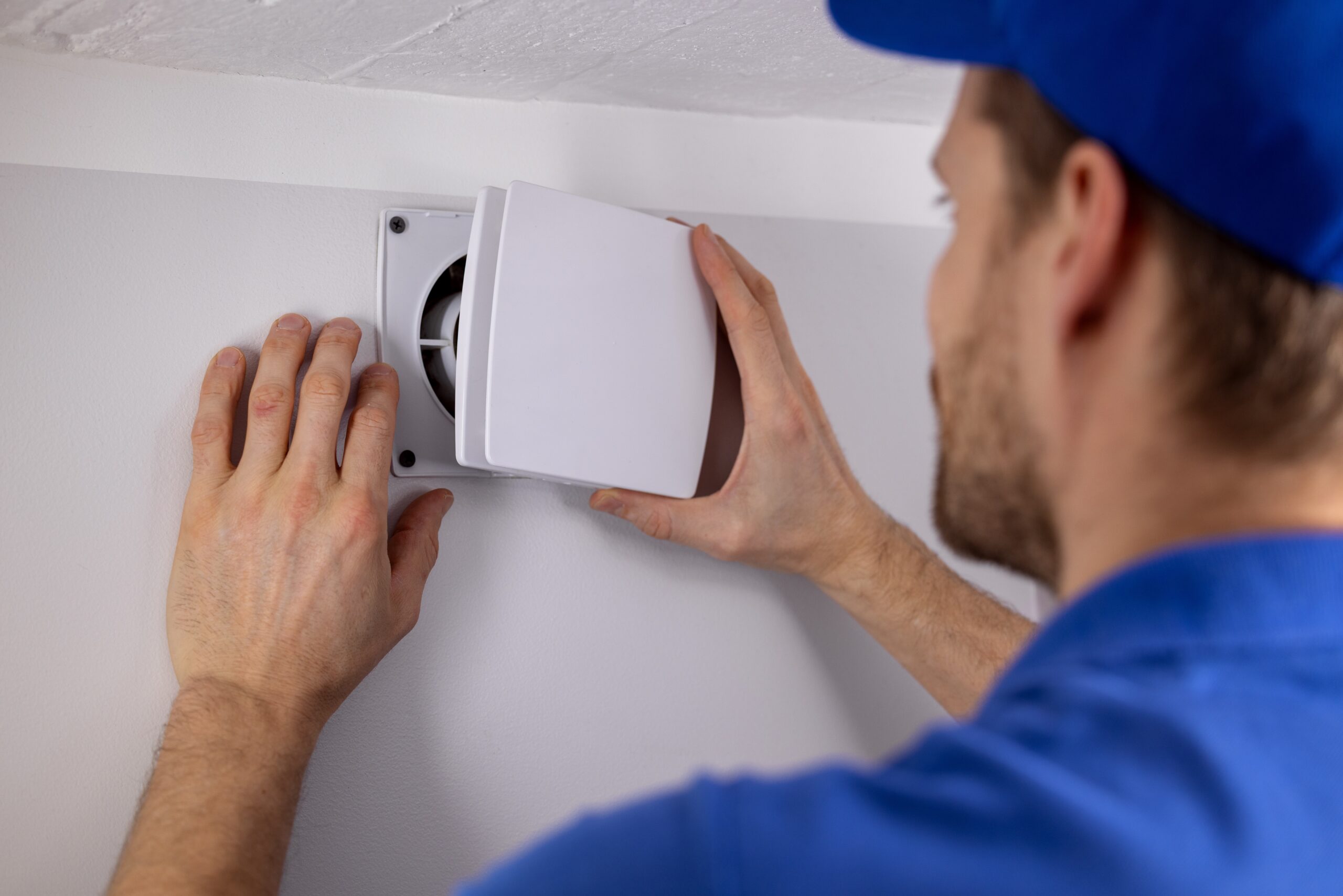
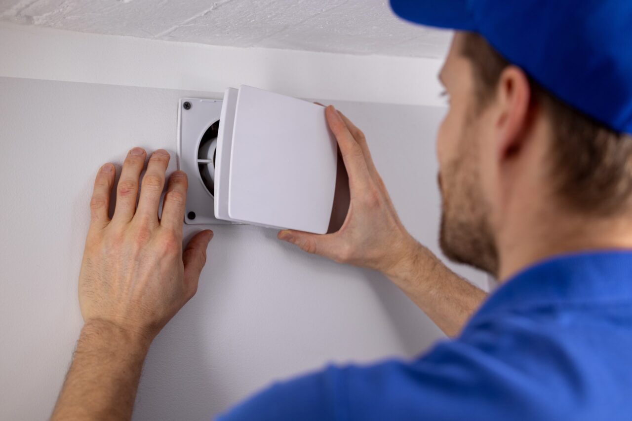
Learning how to install a bathroom exhaust fan addresses one of the most common code violations found in residential inspections. The International Residential Code (IRC) Section R303.3 requires mechanical ventilation in every bathroom that lacks an operable window, and many jurisdictions apply the requirement universally regardless of windows. Moisture from a single hot shower can release two to three pints of water vapor into the air. Without an exhaust fan, that moisture saturates drywall, promotes mold growth behind wall tiles, and accelerates structural wood decay in framing members above the ceiling. The project takes three to five hours for a complete new installation including ductwork, and about two hours for a direct replacement of an existing fan. This guide covers the full process from CFM sizing through duct routing, wiring, and code compliance.
How Bathroom Exhaust Ventilation Works
A bathroom exhaust fan creates negative pressure in the bathroom relative to the rest of the house. The motor spins an impeller (also called a blower wheel or squirrel cage) that draws moist air from the bathroom through the fan housing and pushes it through a duct to the building exterior. As wet, warm air is pulled out, drier air from adjacent rooms flows in under doors and through gaps to equalize pressure. The system works only when the duct terminates outside the building envelope.
Fan performance is measured in cubic feet per minute (CFM), which indicates the volume of air the fan can move. The Home Ventilating Institute (HVI) recommends a minimum of 1 CFM per square foot of bathroom floor area for bathrooms up to 100 square feet. For larger bathrooms, calculate CFM based on the number of fixtures: 50 CFM for each toilet, shower, or bathtub, and 100 CFM for a jetted tub.
Sound level is measured in sones. One sone equals the perceived loudness of a quiet refrigerator running in a kitchen. Fans rated at 0.3 to 1.0 sones are considered whisper-quiet operation. Fans above 3.0 sones are noticeably loud and may discourage regular use, which defeats the ventilation purpose of the installation entirely.
The duct system is critical to fan performance. A fan rated at 80 CFM at 0.1 inches of static pressure will deliver significantly less airflow if the ductwork is undersized, excessively long, or has too many bends. Every 90-degree elbow in the duct run adds the equivalent of approximately 5 feet of straight duct to the system resistance. Flexible duct adds more friction than rigid metal duct of the same diameter. For optimal performance, use rigid or semi-rigid metal duct, keep the run as short and straight as possible, and match the duct diameter to the fan outlet size.
Bathroom Exhaust Fan Comparison
Choosing the right exhaust fan depends on bathroom size, duct run length, and acceptable noise level. The two models below represent the whisper-quiet category at 80 CFM, which meets the ventilation requirement for bathrooms up to 80 square feet. The Broan RB80 uses a standard 4-inch duct connection, a direct fit for retrofit installations with existing 4-inch ductwork. The Panasonic FV-08VQ5 ships with adapters for both 4-inch and 6-inch duct, offering flexibility on retrofit installations where existing ductwork may be either size.
| Feature | Broan RB80 | Panasonic FV-08VQ5 |
| CFM Rating | 80 | 80 |
| Sound Level | 0.3 sones | 0.3 sones |
| Duct Connection | 4″ round | 4″ or 6″ (adapter included) |
| ENERGY STAR Certified | Yes | Yes |
| Housing Dimensions | Fits 2×8 joist bays | Fits 2×8 joist bays |
| Motor Design | Plug-in, field-replaceable | Plug-in, field-replaceable |
| Mounting | New construction or retrofit | New construction or retrofit |
| Best Application | Installations with 4″ ductwork | Flexible duct sizing (4″ or 6″) |
Tools and Materials
- Non-contact voltage tester
- Reciprocating saw or drywall saw
- Drill/driver with hole saw attachment (4″ or 6″ per fan spec)
- Tin snips for sheet metal duct
- Wire strippers rated for 14 and 12 AWG
- Phillips #2 and flat-blade screwdrivers
- Measuring tape and pencil
- Stud finder
- Foil-backed HVAC tape (UL 181 rated, not cloth “duct” tape)
- Rigid or semi-rigid metal duct (4″ or 6″ diameter per fan spec)
- 90-degree metal elbows matching duct size
- Exterior vent cap with backdraft damper
- 14/2 NM-B cable
- Cable clamps
- Wire nuts (yellow for 14 AWG)
- Fan housing with motor and grille assembly
- Single-pole switch or timer switch (60-minute countdown recommended)
- Caulk or fire-rated spray foam for air sealing
- R-8 or higher duct insulation wrap (for attic duct runs)
Step-by-Step: How to Install a Bathroom Exhaust Fan
Step 1: Turn Off the Circuit at the Panel
Identify and switch off the breaker controlling the bathroom circuit. Test the existing light switch and any outlets in the bathroom with a non-contact voltage tester. If installing on a circuit shared with other rooms, verify that all connected outlets are de-energized. For a GFCI-protected bathroom circuit, the upstream GFCI outlet will also lose power. Confirm by pressing the TEST button on the GFCI.
Step 2: Choose the Fan Location
Position the fan as close to the moisture source as possible, ideally directly above or adjacent to the shower or tub. The fan housing must mount between ceiling joists, so locate the joists first using a stud finder. The center of the fan opening should be at least 6 inches from any joist to allow clearance for the housing brackets. Avoid placing the fan directly in the path of shower spray.
Step 3: Mark and Cut the Ceiling Opening
Use the template included with the fan housing (or measure the housing dimensions directly) to mark the ceiling cutout. For drywall ceilings, drill a pilot hole at one corner, then cut along the marked lines with a drywall saw. For plaster ceilings, score the outline with a utility knife first to prevent cracking, then cut carefully with a reciprocating saw fitted with a fine-tooth blade.
Step 4: Access the Attic Space Above the Bathroom
Enter the attic through the access panel or scuttle hole. Locate the ceiling opening from above. If the attic has blown-in insulation, clear it away from the work area. Place a plywood board across the joists as a working platform. Never step between joists, because the drywall below will not support body weight.
Step 5: Plan the Duct Route
Determine the shortest path from the fan location to an exterior wall or the roof. The duct must terminate outside the building envelope. Measure the total duct run length and count the elbows needed. For the Broan RB80, which uses 4-inch duct, keep the run as short and straight as possible, since 4-inch duct has higher air resistance than 6-inch duct. For the Panasonic FV-08VQ5, choose 6-inch duct where possible for lower resistance even though the 4-inch adapter is available.
Step 6: Cut and Install the Exterior Vent Cap
From outside, mark the vent cap location on the wall (for wall termination) or roof (for roof termination). Cut through the sheathing and siding with a hole saw or reciprocating saw sized to match the duct diameter. Insert the vent cap from outside, ensuring the backdraft damper flap opens outward. Seal around the cap flange with exterior-grade caulk. Secure with corrosion-resistant screws. For roof caps, slide the upper flashing edge under the shingles above and over the shingles below.
Step 7: Run the Ductwork from the Vent Cap to the Fan Location
Starting at the exterior vent cap, connect rigid metal duct sections working inward toward the fan location. Use foil-backed HVAC tape (not cloth “duct” tape, which degrades over time in humid conditions) at every joint. Support the duct every 4 feet with metal hangers or straps secured to framing. Maintain a slight slope of 1/4 inch per foot downward toward the exterior to allow condensation to drain out rather than pooling inside the duct or dripping back into the fan housing.
Step 8: Secure the Fan Housing Between the Joists
Extend the adjustable mounting brackets on the fan housing until they contact both joists. Nail or screw the brackets firmly into the joists. The bottom lip of the housing should sit flush with the bottom face of the ceiling drywall. The housing typically has an adjustable depth flange for this purpose. Verify the housing is level before tightening all fasteners.
Step 9: Connect the Ductwork to the Fan Housing
Attach the duct to the fan housing outlet collar. Most housings have a round port with a built-in damper. Slide the duct over the collar and secure with foil-backed HVAC tape and a hose clamp for a positive seal. The connection must be airtight. Any leaks at this joint dump warm, moist air into the attic space instead of exhausting it to the exterior.
Step 10: Run Electrical Cable to the Fan Housing
From the switch box location, run 14/2 NM-B cable through the attic to the fan housing. Staple the cable to joists every 4.5 feet and within 12 inches of each box, per NEC Article 334.30. Insert the cable into the fan housing through the provided knockout and cable clamp. Leave 8 to 10 inches of cable extending inside the housing for connections.
Step 11: Wire the Fan Motor
Inside the fan housing, strip 3/4 inch of insulation from the black and white conductors. Connect the black (hot) wire from the cable to the black fan lead using a wire nut. Connect the white (neutral) wire to the white fan lead. Connect the bare copper ground wire to the green ground screw inside the housing. Tug each wire nut firmly to confirm solid connections.
Step 12: Install the Fan Motor and Grille
Plug the fan motor assembly into the housing receptacle or attach the motor bracket per manufacturer instructions. Both the Broan RB80 and Panasonic FV-08VQ5 use a plug-in motor design that simplifies future motor replacement without entering the attic. Snap or screw the decorative grille onto the housing from below the ceiling.
Step 13: Wire the Wall Switch
At the switch box, connect the incoming power to the switch and the outgoing cable to the fan. The black wire from the fan cable attaches to one switch terminal. The black wire from the incoming power attaches to the other terminal. White wires connect together with a wire nut. Ground wires connect to the switch ground screw and to each other. For a timer switch, follow the manufacturer wiring diagram, as timer switches often require a neutral connection.
Step 14: Restore Power and Test
Turn the breaker back on. Flip the fan switch. Verify the fan spins and air moves through the duct by holding a tissue near the grille. The tissue should be pulled toward the fan and held in place by the airflow. Check at the exterior vent cap to confirm air is exiting and the backdraft damper opens during operation. Listen for unusual noises that might indicate a loose duct connection, motor rubbing, or housing vibration.
Step 15: Insulate and Seal the Ductwork
Wrap the entire duct run in the attic with R-8 or higher duct insulation to prevent condensation from forming on the cold duct surface during winter months. Seal around the fan housing where it meets the ceiling drywall with fire-rated caulk or spray foam. Replace any attic insulation that was displaced during installation. Proper insulation prevents condensation drip-back, which is the leading cause of ceiling stains near exhaust fans.
Sizing a Bathroom Exhaust Fan by Room Volume
The HVI standard for bathroom exhaust fan sizing is straightforward for small bathrooms and more detailed for larger ones.
Bathrooms up to 100 Square Feet: The HVI recommends 1 CFM per square foot of floor area. An 8-foot by 10-foot bathroom (80 square feet) needs an 80 CFM fan. A 7-foot by 7-foot half-bath (49 square feet) needs a 50 CFM fan. Always round up to the next standard fan size. Both the Broan RB80 and the Panasonic FV-08VQ5 are rated at 80 CFM, making them suitable for bathrooms up to 80 square feet.
Bathrooms Over 100 Square Feet: For larger bathrooms, size based on fixture count rather than square footage. Allocate 50 CFM for each standard fixture (toilet, shower, bathtub) and 100 CFM for a jetted tub. A master bathroom with a toilet, separate shower, bathtub, and jetted tub would need 50 + 50 + 50 + 100 = 250 CFM. In these cases, multiple fans or a single high-capacity inline fan may be necessary.
Adjustments for Duct Length: A fan rated CFM is measured under laboratory conditions with minimal duct resistance. Every foot of duct and every elbow reduces actual delivered airflow. For duct runs exceeding 25 feet of equivalent length, upsize the fan by 20 to 30 percent. A bathroom that calculates to 80 CFM with a 40-foot duct run including two elbows should use a 100 CFM or higher fan to account for system losses.
ASHRAE 62.2 Requirements: ASHRAE Standard 62.2 sets a different metric for continuous ventilation. Intermittent bathroom exhaust fans should provide 50 CFM minimum. Continuous exhaust fans should provide 20 CFM. Many modern fans include a “constant ventilation” mode that runs at a low CFM continuously and ramps up to full speed when the switch is activated.
Common Bathroom Exhaust Fan Installation Mistakes
Venting into the Attic: The single most damaging mistake is terminating the exhaust duct inside the attic instead of running it to the building exterior. Warm, moisture-laden air dumped into a cold attic causes condensation on roof sheathing, promotes mold growth on framing, and can rot the roof deck within a few years. IRC Section M1501.1 requires exhaust ducts to terminate outside the building.
Using Flexible Vinyl Duct: Thin, corrugated flex duct creates significant airflow resistance and sags between supports, creating low spots where condensation pools. Over time, vinyl duct can degrade and collapse. Use rigid galvanized metal duct or semi-rigid aluminum duct for the full run.
Oversizing the Ceiling Opening: Cutting a ceiling hole larger than the fan housing creates gaps that allow conditioned air to leak into the attic. This wastes energy and can cause condensation problems at the gap edges. Follow the manufacturer template exactly and measure twice before cutting.
Skipping Duct Insulation in the Attic: Uninsulated duct in an unconditioned attic acts like a cold surface in winter. Warm, moist exhaust air contacting the cold duct walls causes condensation inside the duct. This water runs back toward the fan and drips through the grille onto the bathroom ceiling, leaving stains and potentially damaging drywall. Insulate the full duct run with R-8 or higher duct wrap.
No Backdraft Damper: Without a backdraft damper at the exterior vent cap, outside air flows freely through the duct when the fan is off. In winter, this means cold air entering the bathroom. In humid climates, it means outdoor moisture entering the building. Most quality vent caps include a built-in damper, but verify before purchasing.
IRC and NEC Code Requirements for Bathroom Ventilation
IRC Section R303.3 — Mechanical Ventilation: The IRC requires that all bathrooms have either natural ventilation (an operable window with an aggregate glazing area of not less than 3 percent of the floor area, with at least half the window area operable) or mechanical ventilation (an exhaust fan). Many local jurisdictions require mechanical ventilation regardless of window presence, particularly in climate zones with high humidity or cold winters where opening windows is impractical.
IRC Section M1501.1 — Exhaust Discharge: Exhaust air from bathrooms must discharge to the outdoors through a duct system. The duct cannot terminate in an attic, crawlspace, soffit, or any other indoor or enclosed space. The termination point must have a backdraft damper or gravity damper to prevent reverse airflow.
NEC Article 210.8(A)(1) — GFCI Protection: All 125-volt, 15- and 20-ampere receptacle outlets in bathrooms require GFCI protection. While the NEC does not explicitly require GFCI protection for a hardwired exhaust fan circuit (it is not a receptacle outlet), many local codes extend the GFCI requirement to all bathroom circuits. Check with the local authority having jurisdiction.
NEC Article 334.30 — NM Cable Securing: NM-B cable must be secured within 12 inches of every box and at intervals not exceeding 4.5 feet along the run. Cable staples must not damage the cable jacket. Use appropriate cable clamps at the fan housing and switch box.
IRC Section M1507.2 — Minimum Airflow: Intermittent bathroom exhaust fans must provide a minimum of 50 CFM. Continuous exhaust fans must provide a minimum of 20 CFM. These are minimums. For rooms larger than 50 square feet, the HVI 1 CFM per square foot guideline produces higher values.
Duct Routing and Termination Best Practices
Route Through the Shortest Path: The ideal duct run goes straight up from the fan housing through the roof, or straight out through an adjacent exterior wall. Every additional foot of duct and every bend reduces delivered airflow. When routing through the attic, avoid running duct parallel to long joist bays if a shorter perpendicular route reaches an exterior wall.
Maintain Proper Slope: Slope the duct 1/4 inch per foot downward toward the exterior termination point. This prevents condensation from pooling inside the duct or running back toward the fan housing. On roof-penetration installations where the duct must rise, use a drip tee at the low point to catch condensation before it reaches the fan.
Seal Every Joint: Use foil-backed HVAC tape (marked UL 181A-P or UL 181B-FX) at every duct connection. Standard cloth “duct tape” dries out, loses adhesion, and fails within a few years. Mastic sealant is even better for permanent joints. Apply a continuous bead around each joint and smooth with a brush.
Choose the Right Termination: Wall caps work best for short duct runs on exterior walls. Roof caps are better for interior bathrooms where the duct must traverse the attic. Avoid terminating near soffit vents, as the exhausted moisture can be drawn back into the attic through the soffit intake. Maintain at least 3 feet of separation between the exhaust termination and any air intake.
Match Duct Size to the Fan: Never reduce the duct size below the fan outlet diameter. The Broan RB80 has a 4-inch outlet. The Panasonic FV-08VQ5 ships with adapters for both 4-inch and 6-inch duct. Using 6-inch duct delivers lower air resistance and better performance, especially on longer runs.
Frequently Asked Questions
Q: What CFM rating is needed for a bathroom exhaust fan?
A: The HVI recommends 1 CFM per square foot of bathroom floor area for rooms up to 100 square feet. A standard 5-foot by 8-foot bathroom (40 square feet) needs a minimum 50 CFM fan. An 8-foot by 10-foot bathroom (80 square feet) needs an 80 CFM fan. The Broan RB80 and Panasonic FV-08VQ5 both deliver 80 CFM, covering most standard bathrooms.
Q: Can a bathroom exhaust fan be vented through an exterior wall instead of the roof?
A: Yes. Wall termination is often preferred because it keeps the duct run shorter and avoids a roof penetration. Use a wall cap with a built-in backdraft damper. The wall cap should be positioned at least 10 inches above the finished grade on the exterior and at least 3 feet from any air intake, operable window, or soffit vent to prevent re-entrainment of the exhausted moisture.
Q: Is a GFCI circuit required for a hardwired bathroom exhaust fan?
A: NEC Article 210.8(A)(1) requires GFCI protection for receptacle outlets in bathrooms, not for hardwired appliances. However, many local codes extend the GFCI requirement to all circuits in the bathroom, including hardwired fans. Check with the local building authority. Even where not required, GFCI protection on the fan circuit adds a safety margin, especially when the fan is located above a shower. For installation guidance, see How to Install a GFCI Outlet: Step-by-Step Wiring Guide on the SupplyHouse blog.
Q: How far can ductwork run from a bathroom exhaust fan to the exterior vent?
A: Maximum duct length depends on the fan model, duct diameter, and the number of elbows. As a general rule, rigid 6-inch duct can run up to 90 equivalent feet (straight duct plus elbow equivalents). Each 90-degree elbow adds approximately 5 equivalent feet. For duct runs exceeding 25 equivalent feet, increase the fan CFM by 20 to 30 percent above the calculated minimum.
Q: Can a bathroom exhaust fan be installed directly above a shower?
A: Yes, but the fan must be rated for damp or wet locations if installed within the shower enclosure. Fans installed directly above a shower stall (within the shower footprint) should carry a UL or ETL listing for installation in wet locations. Fans installed in the ceiling outside the shower footprint but in the general bathroom area only need a damp-location rating, which most standard bath fans carry.
Q: What size duct should be used for a bathroom exhaust fan?
A: Always use the duct diameter specified by the fan manufacturer. The Broan RB80 requires 4-inch duct. The Panasonic FV-08VQ5 includes adapters for 4-inch or 6-inch duct, but 6-inch delivers better performance due to lower air resistance. Never reduce the duct size below the fan outlet diameter.
Q: How loud is a bathroom exhaust fan rated at 1.0 sones?
A: One sone is approximately equivalent to the sound of a quiet refrigerator running in a kitchen. Fans at 0.3 sones, like the Broan RB80 and Panasonic FV-08VQ5, are barely audible during normal conversation. Fans rated at 2.0 to 3.0 sones are noticeably present. Fans above 4.0 sones are loud enough that many occupants avoid using them, which undermines the ventilation purpose.
Q: Can one exhaust fan serve two separate bathrooms?
A: A single high-capacity inline fan can serve multiple bathrooms through a branched duct system, but all open branches normally exhaust whenever the central fan runs. Independent branch operation requires a manufacturer-approved control and damper arrangement. The fan CFM must equal the combined requirement of all connected bathrooms. This approach requires careful duct design and is more common in commercial than residential applications.
Q: Should a bathroom exhaust fan be connected to a timer switch?
A: A timer switch is one of the most effective upgrades for a bathroom exhaust fan installation. The fan should run for at least 20 minutes after the shower ends to fully remove residual moisture. A 60-minute countdown timer ensures adequate run time without leaving the fan on indefinitely. Humidity-sensing switches are another option, activating the fan automatically when moisture levels rise and shutting off when the air dries.
Q: What happens if a bathroom has no exhaust fan or operable window?
A: Without ventilation, moisture from bathing accumulates on surfaces and within wall and ceiling cavities. Over time, this creates conditions for mold growth, which appears as black or green spots on grout, caulk, and ceiling paint. In severe cases, moisture penetrates behind tiles and into wall framing, causing wood rot and structural damage. IRC Section R303.3 requires mechanical ventilation for this reason. Browse the full selection of exhaust fans at supplyhouse.com/Bathroom-Exhaust-Fans-34360000 to find the right CFM and sound level for any bathroom.
Clear the Air Before It Clears the Ceiling Paint
A properly installed bathroom exhaust fan prevents years of moisture damage and keeps indoor air quality where it belongs. The Broan RB80 and Panasonic FV-08VQ5 both deliver 80 CFM at a whisper-quiet 0.3 sones, which means the fan actually gets used instead of sitting idle because it sounds like a jet engine. Sizing starts at 1 CFM per square foot, ductwork runs to the exterior through the shortest path possible, and every joint gets sealed with foil-backed HVAC tape. Find these fans and a full range of ventilation accessories at supplyhouse.com/Bathroom-Exhaust-Fans-34360000. For the electrical side of the project, especially GFCI protection on the bathroom circuit, the guide How to Install a GFCI Outlet: Step-by-Step Wiring Guide covers the wiring details. Clear the moisture before it clears the ceiling paint.