What a Pressure-Reducing Valve Actually Does
A PRV is a spring-loaded diaphragm valve installed on the main water supply line, downstream of the meter and the main shutoff. Its job is to sense downstream pressure and modulate the valve opening to maintain a consistent, lower outlet pressure regardless of fluctuations in the inlet supply.
Most residential PRVs are factory-set at 50 PSI and are adjustable in a range of 25 to 75 PSI. The Watts LFN45B series, for example, handles inlet pressures up to 400 PSI and can be set anywhere in that 25-to-75 PSI window. Set it to 60 PSI, and 60 PSI is what the system sees, whether the street pressure spikes to 120 PSI at 3 a.m. or sits at 75 PSI during peak demand hours.
One thing PRVs don’t do on their own: relieve thermal expansion pressure created by water heaters and closed-loop systems. A potable water expansion tank is the correct companion for that problem, not a higher PRV setpoint.
Tools and Materials Checklist
Before touching a pipe, have everything staged. Stopping mid-install to make a supply run costs more time than the prep.
| Item | Notes |
| PRV (sized to pipe diameter) | Lead-free, NSF 61/372 certified for potable water |
| Isolation ball valves (x2) | Full-port, one upstream and one downstream of PRV |
| Pressure gauge (0-100 PSI) | Installed downstream to verify setpoint |
| Thread sealant or PTFE tape | Applied to all male threads |
| Pipe wrench and adjustable wrench | For union connections and adjusting screw |
| Bucket and shop towels | System will drain when the main is shut off |
| Flathead screwdriver or hex key | Depends on manufacturer’s adjustment cap style |
Shop pressure-reducing valves andfull-port ball valves at SupplyHouse.
Choosing the Right PRV for the Job
Size and certification matter more than brand loyalty here. Get these three things right:
- Pipe size match: 3/4″ is standard for most residential mains. 1″ is common for larger homes or light commercial. The PRV inlet and outlet must match the line size, not create a reduction.
- Lead-free construction: Any PRV installed on a potable water line must meet NSF 61 and NSF 372 (lead-free) standards. Verify the certification before ordering.
- Connection style: Union connections on both sides allow the PRV body to be removed for service or replacement without cutting pipe. Always specify union-end or double-union models
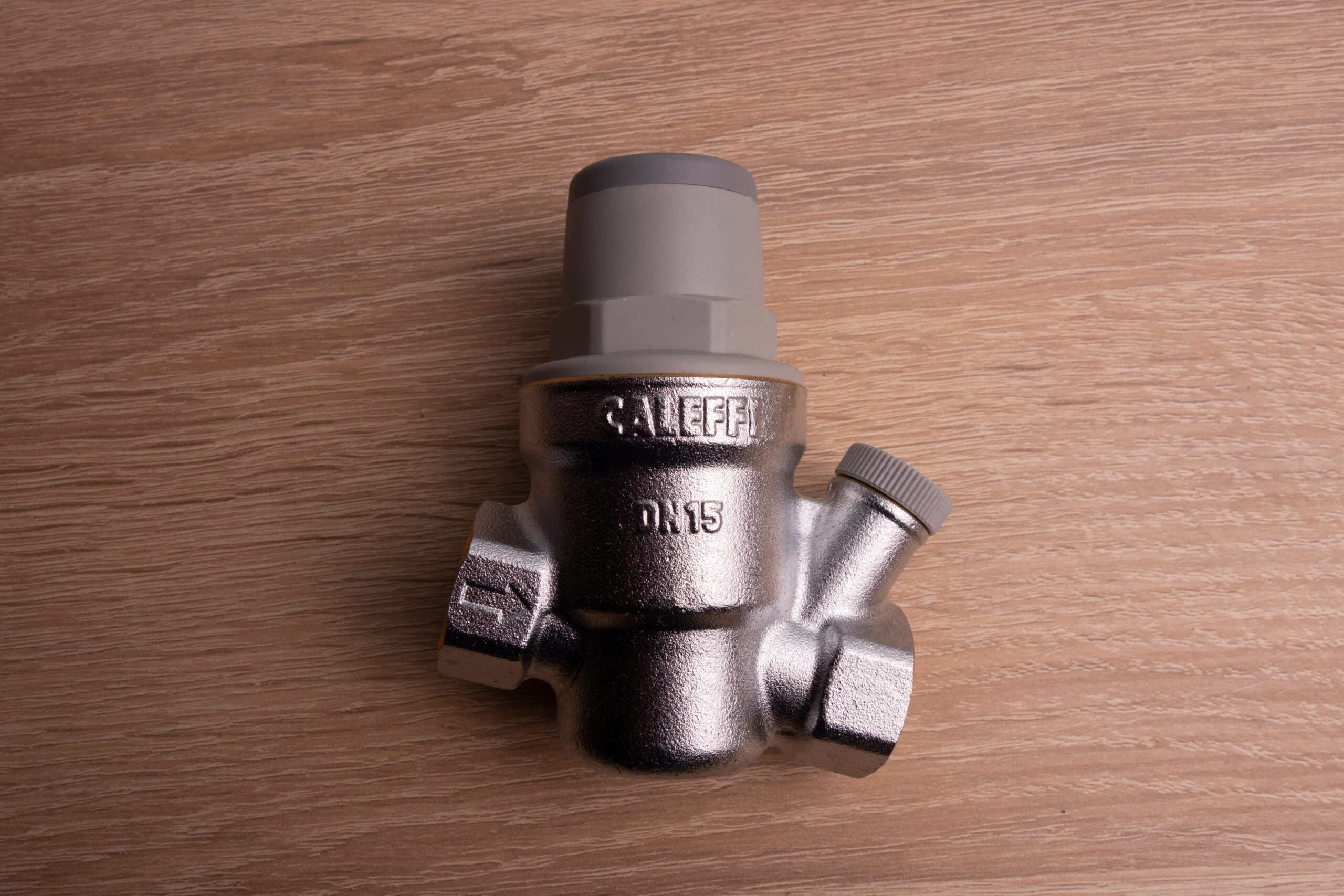
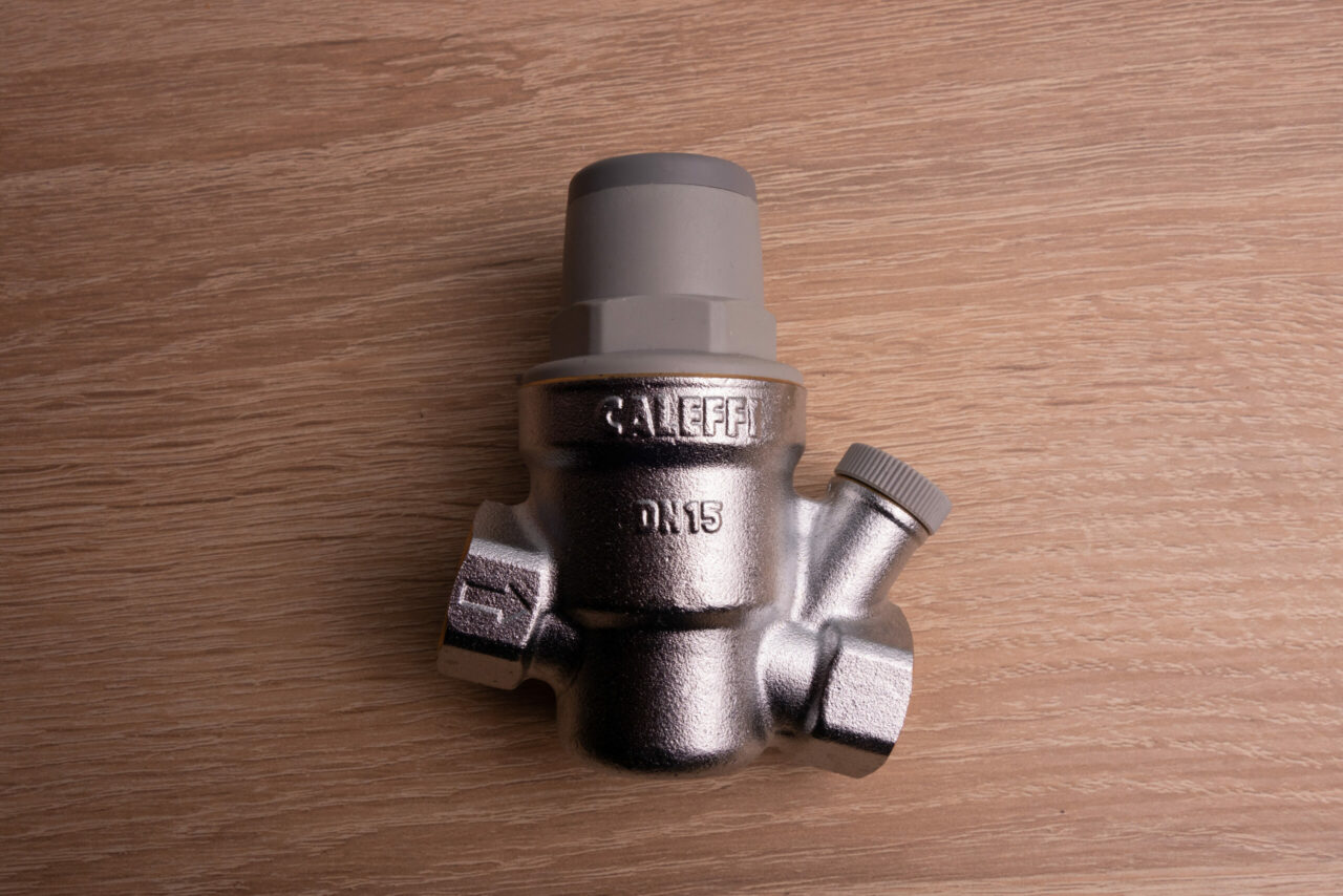
The Watts 3/4″ LFN45BM1 Water Pressure Reducing Valve handles inlet pressures up to 400 PSI, adjusts from 25 to 75 PSI, and includes an integral stainless steel strainer. The 1″ version with union inlet is the Watts LFN45BM1-U. For press-connection installs, the Caleffi 535681HA 1-1/2″ PRV with integral gauge is a solid choice on larger residential and light commercial systems.
| PRV Size | Typical Application | Max Flow (GPM) |
| 1/2″ | Single-fixture or isolated branch | ~8 GPM |
| 3/4″ | Standard residential main | ~20 GPM |
| 1″ | Larger home or light commercial | ~32 GPM |
| 1-1/4″ to 1-1/2″ | Commercial / multi-unit | ~42-60 GPM |
Where to Install the PRV
Location isn’t complicated, but placement mistakes cause problems that are annoying to fix after the walls are closed up.
- After the main shutoff, before the first branch: The PRV protects everything downstream. Install it on the main supply line, just past the main ball valve shutoff, before any branch tees to hose bibbs, water heaters, or interior plumbing.
- Before the water heater: Pressure reduction needs to happen before the water heater, not after. The expansion created by heating water at unregulated pressure is what waterlogged expansion tanks, weeping T&P valves, and failed appliances come from.
- Accessible location: PRVs have a strainer that should be cleaned periodically and a diaphragm that eventually wears. Install somewhere that doesn’t require a full tear-out to access
- Orientation: Most spring-diaphragm PRVs are designed for horizontal installation with the bonnet (adjustment cap) facing up or to the side. Check the manufacturer’s installation instructions. Installing upside down traps debris in the chamber and accelerates wear.
The plumbing code in most jurisdictions places PRVs on the service entry line of any structure where the street pressure exceeds 80 PSI. Even where it isn’t mandated, it’s good practice anywhere the meter pressure runs above 60 PSI.
Step-by-Step Installation
Work through each step in order. There’s no shortcut worth taking on a pressurized water line.
- Shut off the main water supply. Close the main shutoff valve at the meter or where the supply enters the structure.
- Open a downstream faucet. Open a faucet at a low point in the system to relieve pressure and allow the line to drain. Have towels and a bucket at the installation point.
- Mark the flow direction. PRVs are directional. The arrow cast into the body must point in the direction of water flow, from the street toward the structure. Double-check before cutting.
- Cut the pipe and remove the section. Allow enough clearance for the PRV body plus the union connections on both sides. Measure the PRV’s end-to-end length with unions assembled before cutting.
- Install upstream isolation valve. Thread or solder a full-port ball valve upstream of the PRV location. This valve allows isolation of the PRV without shutting off the entire structure.
- Apply thread sealant and install the PRV. Wrap all male NPT threads with two to three wraps of PTFE tape, or use a paste thread sealant rated for potable water. Thread the PRV into position, hand-tight first, then wrench-tighten. Do not over-torque brass bodies.
- Install downstream isolation valve and pressure gauge port. Install a second full-port ball valve downstream of the PRV. Between the PRV outlet and the downstream ball valve, add a tee with a 1/4″ NPT pressure gauge port. This is where the gauge goes for pressure verification and future adjustment.
- Slowly restore water supply. Open the main shutoff slowly to allow the system to repressurize gradually. Check all connections for leaks before fully opening the valve.
- Check initial downstream pressure. With the downstream ball valve open and a faucet slightly open downstream, read the gauge. Most PRVs ship at 50 PSI from the factory.
- Adjust to target setpoint. See the adjustment procedure in the next section.
Need a reliable gauge for verification? The Watts LFDPG1 2-1/2″ Lead-Free Pressure Gauge (0-100 PSI) reads the full adjustment range and is approved for potable water systems. The FPPI Water Pressure Gauge Kit includes the fittings needed to connect a gauge to an existing system quickly.
How to Set and Adjust the Pressure
The adjustment mechanism on most residential PRVs is a spring-loaded screw under a cap or lock nut on the top of the bonnet. Clockwise raises the setpoint. Counter-clockwise lowers it. The process takes about two minutes with a gauge and the right screwdriver.
-
-
- Identify the target setpoint. For residential potable water, 55 to 65 PSI is the working range for most systems. Fixtures are typically rated to 80 PSI maximum. Set the PRV to 60 PSI as a baseline unless there’s a specific reason to go higher or lower.
-
- Remove the adjustment cap. The cap protects the adjustment screw from tampering. It may thread off or unclip, depending on the model.
-
- Loosen the lock nut (if present). Some models have a hex nut that locks the adjustment screw in place. Back it off before turning the adjustment screw.
-
- Turn the adjustment screw and monitor the gauge. With water flowing slowly through an open downstream faucet, turn the screw clockwise to increase pressure or counter-clockwise to decrease it. Make small turns, half a revolution at a time, and watch the gauge settle before making additional adjustments.
-
- Verify at no-flow (static) conditions. Close the downstream faucet and let the system sit for two to three minutes. Read the static pressure. Static pressure will typically read 3 to 8 PSI higher than dynamic (flowing) pressure. If static pressure is acceptable, re-tighten the lock nut.
- Replace the adjustment cap. Reinstall the protective cap to prevent accidental or unauthorized adjustment.
-
| Application | Recommended Setpoint | Notes |
| Standard residential | 55-65 PSI | Balances fixture performance and pipe longevity |
| Older home with galvanized pipe | 45-55 PSI | Lower pressure reduces stress on corroded fittings |
| High-rise or multi-story residential | 65-70 PSI | Accounts for pressure loss to upper floors |
| Water heater with expansion tank | Per tank pre-charge | PRV setpoint should match tank pre-charge pressure |
| Commercial dishwasher or booster pump | Per equipment spec | Check appliance documentation for required inlet pressure |
The PRV and Thermal Expansion: What to Know
Installing a PRV on a system with a water heater creates what’s called a closed system. The PRV prevents pressure from venting back toward the meter. When the water heater runs, the water expands. In a closed system, that expansion has nowhere to go.
The T&P valve is the last line of defense, not the pressure management strategy. Install a potable water expansion tank on the cold-water supply line near the water heater any time a PRV is installed on a system with a direct-fired water heater. Pre-charge the expansion tank air side to match the PRV setpoint. If the PRV is set to 60 PSI, the tank pre-charge should be 60 PSI.
Local codes in most jurisdictions now require the expansion tank wherever a closed system exists. The PRV creates the closed system. Don’t skip the tank.
Common Installation Mistakes
- Installing without downstream isolation: Without a ball valve downstream of the PRV, any service or replacement requires shutting off the entire main. Add both isolation valves during the initial install.
- Skipping the pressure gauge: Adjusting a PRV by feel or by counting turns on the adjustment screw produces inconsistent results. A downstream gauge is not optional.
- Installing the PRV in the wrong direction: The arrow on the body must align with flow direction. Backward installation results in either no flow or no pressure reduction. Check twice before cutting.
- Forgetting the expansion tank: A PRV plus a water heater plus no expansion tank equals a T&P valve that pops regularly and eventually fails.
- Setting the pressure too low: Residential water heaters typically require at least 20 PSI inlet pressure to function correctly. Fixtures at upper floors need enough pressure to function after static head loss (roughly 0.43 PSI per foot of elevation). Setting too low creates low-pressure complaints faster than the callbacks from running too high.
Maintenance and Service Intervals
A properly installed PRV is largely set-and-forget for several years. The strainer screen is the part that requires periodic attention in areas with hard water or sediment in the supply.
Most union-connected PRVs can be serviced in-line without removing the body from the pipe. The strainer module typically unthreads from the bottom of the body. Flush the screen, reinstall, and verify setpoint hasn’t drifted after reassembly.
| Service Item | Interval | Procedure |
| Strainer screen inspection | Annually or after water quality event | Isolate PRV, relieve pressure, remove strainer cap, clean screen |
| Downstream pressure check | Annually | Connect gauge to test port, verify setpoint under dynamic conditions |
| Diaphragm / cartridge replacement | Every 8-12 years or when setpoint won’t hold | Remove bonnet assembly, replace internals, re-set pressure |
| Full PRV replacement | Every 15-20 years or on failure | Isolation valves allow replacement without major disruption |
Browse plumbing valves and plumbing test equipment at SupplyHouse for everything needed to service and verify PRV performance.
Frequently Asked Questions
What PSI should a residential PRV be set to?
For most residential systems, 55 to 65 PSI is the target range. It’s low enough to protect appliances and plumbing from long-term pressure fatigue, and high enough to deliver adequate flow on upper floors and to appliances with minimum pressure requirements. If the water heater manufacturer specifies a minimum inlet pressure, don’t go below it.
Can a homeowner install a PRV, or does it require a licensed plumber?
Licensing requirements vary by jurisdiction. Many states allow homeowners to replace or install plumbing fixtures in their own residence. Some jurisdictions require a permit and inspection for any work on the service entry line. Check local code before starting.
How do I know if my system needs a PRV?
The simplest test is a hose bib pressure gauge on an outdoor spigot. Static (no-flow) pressure above 80 PSI means the system needs regulation. Noisy pipes, appliances cycling on and off rapidly, and T&P valves that drip regularly are also indicators of excess supply pressure.
Does a PRV affect hot water pressure?
Yes. The PRV controls inlet pressure to the entire structure, including the cold-water feed to the water heater. The water heater then distributes hot water at that pressure. Properly set, a 60 PSI setpoint delivers adequate pressure to all hot and cold fixtures in a standard residential application.
What’s the difference between a pressure-reducing valve and a pressure-regulating valve?
The terms are used interchangeably in residential and commercial plumbing. Both refer to the same type of device: a spring-diaphragm valve that reduces and regulates downstream pressure from a higher-pressure supply.
Can the PRV be installed vertically?
Some models can be installed vertically, but most standard spring-diaphragm PRVs are designed for horizontal pipe runs with the bonnet up. Always check the manufacturer’s installation instructions before orienting the valve outside of the horizontal position.
My downstream pressure keeps climbing above the setpoint. What’s wrong?
Pressure creep above setpoint in a closed system is almost always thermal expansion, not a failed PRV. The water heater heats the water, pressure rises, and with no path to relieve it, the gauge climbs. Install an expansion tank sized to the system and pre-charged to the PRV setpoint. If pressure creep continues with an expansion tank installed, the tank may be waterlogged (failed bladder) and needs replacement.
Do I need a PRV if I’m on a private well?
Possibly. Well systems typically run with a pressure switch set to cycle between 40 and 60 PSI or 50 and 70 PSI. At the high end of the cycle, pressure can reach 70+ PSI. In most well systems, a PRV isn’t required unless there’s a specific fixture or appliance with a maximum inlet pressure below the pump’s cut-off pressure.
How much inlet pressure can a standard residential PRV handle?
The Watts LFN45B series, which covers most residential applications, is rated for inlet pressures up to 400 PSI. Street pressure in the U.S. rarely exceeds 150 PSI. The 400 PSI rating provides ample safety margin for any residential supply condition.
Should the expansion tank pre-charge match the PRV setpoint exactly?
Yes. The expansion tank air-side pre-charge should match the cold-water static pressure at the tank location, which is the PRV setpoint. If the pre-charge is lower than the incoming water pressure, the diaphragm deflects immediately on fill and the tank provides no useful absorption volume. If it’s higher, the tank won’t accept any expansion volume until system pressure rises above the pre-charge, which effectively defeats the purpose.
Wrap-Up
High supply pressure doesn’t announce itself. It works quietly, cycling appliances too hard, fatiguing fittings slowly, and eventually showing up as a waterlogged expansion tank, a cracked washing machine hose, or a T&P valve that won’t stop weeping. A pressure-reducing valve, properly installed and set, eliminates all of that for the cost of an afternoon and a straightforward job.
Install isolation valves on both sides. Add a gauge port downstream. Set the PRV to 60 PSI as a starting point and adjust from there with the gauge in hand. If there’s a water heater downstream, add the expansion tank.