
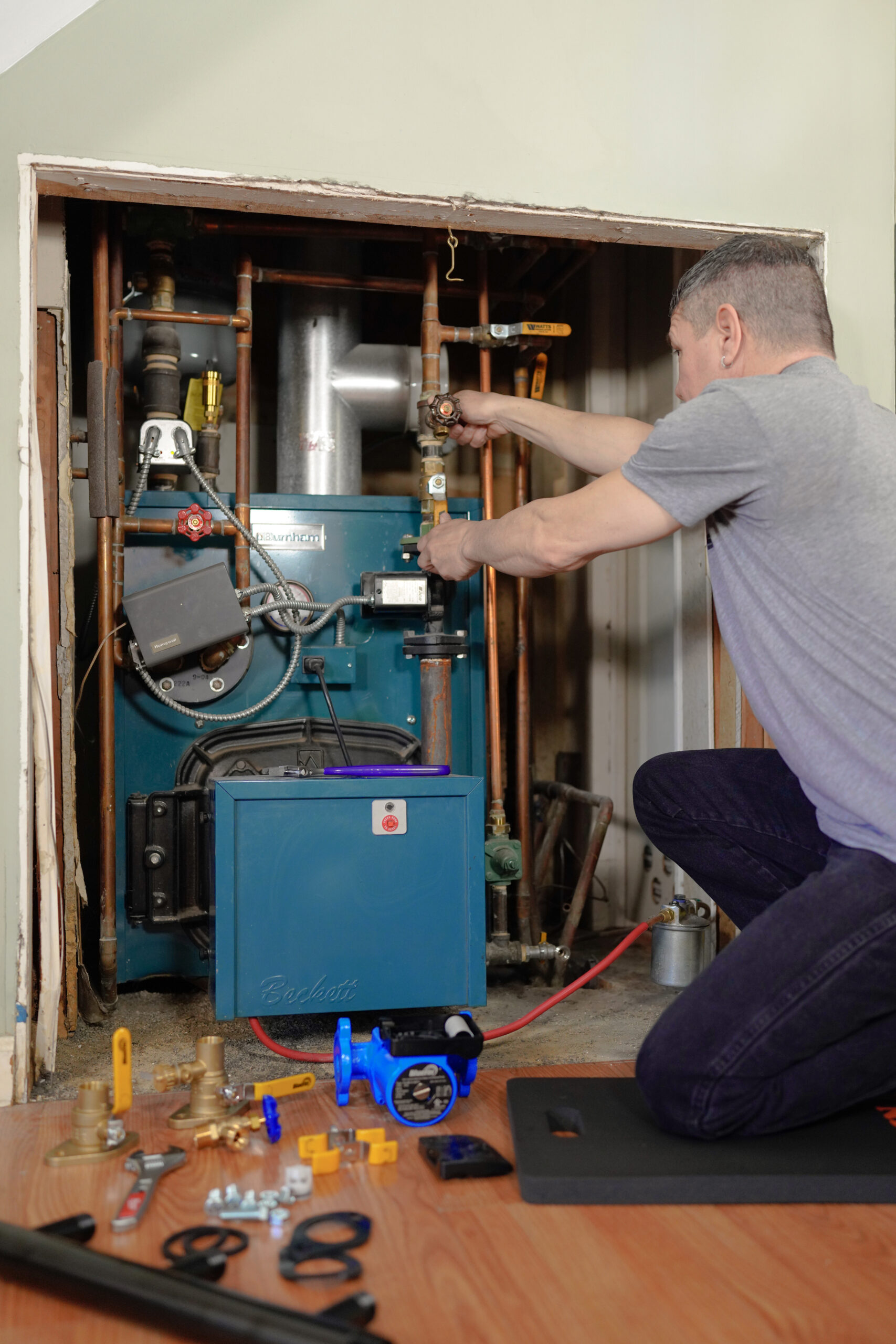
Replacing a boiler is not a Tuesday afternoon job. It involves live gas or oil lines, pressurized systems, electrical wiring, code-required safety controls, and a homeowner who has been without heat long enough to start asking questions. The difference between a clean installation and a callback-heavy nightmare almost always comes down to sequence: doing the right things in the right order, starting before the truck pulls up.
This guide walks through the full residential boiler installation process from pre-job assessment through first-fire commissioning. It covers what to verify on the job site, how near-boiler piping should be laid out, which safety controls are code-required and why, how venting and combustion air requirements differ by boiler type, and what a proper startup looks like before the homeowner walks back in.
Before the Job: Site Assessment and Pre-Installation Planning
Showing up to an installation without doing homework first is a good way to make two trips out of a one-trip job. Proper pre-installation assessment covers four areas: load confirmation, existing system condition, boiler room requirements, and permit status.
Confirm the Heat Loss Calculation
The boiler output needs to match the building load, not the nameplate on the unit being replaced. Older boilers were routinely oversized by 25 to 40 percent. Swapping in the same BTU capacity perpetuates that mistake. Run a proper Manual J heat loss calculation before selecting the new unit. Residential buildings in cold climates generally fall between 40 and 60 BTU/hr per square foot. A 2,000 sq ft home in the Northeast typically carries a design load between 80,000 and 120,000 BTU/hr depending on insulation and window area.
Inspect the Existing System
Before any new equipment goes in, evaluate what is already there. Check the following:
- Existing piping material, diameter, and condition. Galvanized steel in an older system may be scaled and restrictive. Document it.
- Expansion tank type and size. An old closed steel tank is almost certainly waterlogged and needs replacement. Size the new diaphragm or bladder type per the manufacturer chart. The Amtrol #30 Extrol (SKU: 102-1) is factory pre-charged to 12 psig and covers most residential hydronic systems up to 4.4 gallons.
- Circulator pump condition and sizing. Confirm GPM capacity against the new boiler’s minimum flow requirement.
- Zone valve and zone pump operation. Stuck zone valves are a common source of no-heat calls after a boiler change.
- Existing boiler room clearances and floor condition. Most manufacturers require a level, solid, non-combustible floor.
Verify Permits and Code Jurisdiction
A boiler installation without a permit is a liability. Most jurisdictions require a mechanical permit, a gas line permit if the gas piping is being modified, and an electrical permit if new wiring is pulled. Many municipalities require a licensed contractor of record, inspection before backfill or wall closure, and a CO test after commissioning. Contact the local authority having jurisdiction (AHJ) before the job starts.
Removing the Old Boiler
Decommissioning the existing unit has to be done safely and in the right sequence.
- Call the gas utility if the gas service needs to be interrupted. Do not cap a live gas line without utility authorization in jurisdictions that require it.
- Turn off all fuel supply valves and electrical disconnect to the existing boiler.
- Attach a hose to the boiler drain and drain the system. If the system uses antifreeze, dispose of it properly.
- Disconnect gas piping using approved fittings and cap all open lines immediately.
- Disconnect flue breeching and inspect the chimney liner or vent pipe for deterioration. A deteriorated B-vent liner is a carbon monoxide risk. Address it before the new boiler goes in.
- Disconnect electrical supply and zone wiring. Label every wire before pulling it.
- Disconnect supply and return water connections at the boiler. Cap all open piping.
- Remove and dispose of the old unit per local regulations. Cast iron sections are heavy. Use pipe dollies and appropriate rigging.
Boiler Room Setup: Clearances and Combustion Air
Minimum Clearances
Every manufacturer specifies minimum clearances to combustibles in the installation manual. These are non-negotiable. Typical requirements for a residential gas-fired cast iron boiler per Weil-McLain EG Series documentation:
| Side | Minimum Clearance | Notes |
| Front (service access) | 24 inches preferred; check manufacturer spec | Required for burner service |
| Sides | 6 inches minimum | May reduce with close-clearance kit |
| Rear | 6 inches minimum | Verify in model-specific manual |
| Vent pipe to combustibles | 6 inches for double-wall B-vent; 9 inches for single-wall | Per Weil-McLain and NFPA 211 |
| Floor | Most manufacturers permit combustible flooring; verify model-specific requirements | Some oil boilers require concrete or masonry |
Always use the clearances published in the specific boiler’s installation manual. Close-clearance kits are available for some models where space is genuinely constrained, but these require specific installation procedures and are not a generic workaround.
Combustion Air Requirements
Insufficient combustion air leads to incomplete combustion, carbon monoxide production, draft problems, and burner lockouts. Per NFPA 54, a space is considered confined if it contains less than 50 cubic feet of volume per 1,000 BTU/hr of combined appliance input. A 100,000 BTU boiler in a mechanical room smaller than 5,000 cubic feet is in a confined space and requires dedicated combustion air provisions.
For confined spaces with gas appliances, NFPA 54 requires two permanent openings:
- One opening commencing within 12 inches of the ceiling.
- One opening commencing within 12 inches of the floor.
- Communicating to adjacent unconfined indoor space: minimum 1 square inch of free area per 1,000 BTU/hr of input for each opening.
- Communicating directly to outdoors: minimum 1 square inch of free area per 4,000 BTU/hr of input for each opening.
Direct-vent (sealed combustion) boilers draw all combustion air from outside through a dedicated pipe and are not subject to the room volume calculations above. For these units, the combustion air pipe is part of the venting assembly and must be installed per the manufacturer’s specifications.
Setting and Connecting the New Boiler
Positioning and Leveling
Move the boiler into position before connecting anything. Cast iron boilers are extremely heavy. Use a furniture dolly or pipe rollers; never drag a boiler on casters under load. Level the boiler in both directions before piping begins. An out-of-level boiler causes drainage and gauge reading problems.
For knocked-down cast iron boilers assembled on-site, follow the manufacturer’s section assembly instructions exactly. Sections must have metal-to-metal contact around port openings. Any gap exceeding 0.020 inches indicates a problem with section alignment or damaged push nipples.
Hydrostatic Pressure Test
Before connecting any controls or gas piping, perform a hydrostatic pressure test. Per Weil-McLain documentation:
- Plug all boiler tappings except those used for fill and vent. Do not use the pressure gauge supplied with the boiler for pressure testing; install a separate test gauge.
- Fill the boiler with water and vent all air.
- For hot water boilers: test at 1.5 times MAWP. Most residential hot water boilers carry a 30 psig MAWP, so the hydrostatic test runs at approximately 45 psig for a minimum of 10 minutes.
- For steam boilers: test between 45 and 55 psig.
- Check for maintained gauge pressure and inspect for leaks. Any leak must be repaired before proceeding.
- After testing, drain and install controls per the manufacturer’s instructions.
Near-Boiler Piping
Near-boiler piping is where most installation problems originate. Get this wrong and the system will short cycle, make noise, have chronic air problems, or fail to maintain consistent pressure. The sequence of components matters.
Required Safety Controls
These are not optional. Every residential hot water boiler installation requires the following:
| Component | Function | Code Basis / Example SKU |
| Pressure/temperature gauge | Shows system pressure and supply water temperature | Required per ASME Section IV and most manufacturer manuals |
| Pressure relief valve | Opens if system pressure exceeds MAWP (30 psig typical). Watts M335M2-030 (SKU: 0342692) is a common 3/4″ 30 psi boiler PRV rated for up to 510,000 BTU. | ASME BPV Code Section IV, HG-701 |
| Low water cutoff (LWCO) | Shuts burner if water level drops below safe operating level. Taco LTA1203S-2 (SKU: LTA1203S-2) is a probe-style electronic LWCO with auto-reset at 120V. | Required by most state and local codes for automatically-fired boilers |
| High limit aquastat | Shuts burner if supply water temperature exceeds set point (typically 180-220 degrees F). Factory-set on most modern boilers. | Required per NFPA 54 and ASME Section IV HG-605 |
| Expansion tank | Absorbs thermal expansion of system water. Amtrol EX-30 (SKU: 102-1) is factory pre-charged to 12 psig. | Required for all closed hydronic systems |
| Air eliminator | Removes dissolved air continuously during operation. Spirotherm Spirovent Jr. 1″ (SKU: VJR100) installs on the supply side near the boiler outlet. | Prevents chronic air problems, cold zones, and noisy piping |
The relief valve discharge pipe must be full-port Schedule 40 metal pipe run to within 6 inches of the floor or to an appropriate drain. No shut-off valve may be installed in the discharge line.
Near-Boiler Piping Sequence
For a typical single-zone hot water system, the supply side sequence runs:
- Boiler supply outlet
- Air eliminator: Spirotherm Spirovent Jr. 1″ (SKU: VJR100) at the highest water temperature, lowest velocity point near the boiler outlet.
- Expansion tank tee: immediately downstream of the air eliminator to establish the system point of no pressure change. Amtrol EX-30 (SKU: 102-1) is pre-charged to 12 psig.
- Circulator pump: Taco 007-F5-7IFC (SKU: 007-F5-7IFC) is a 1/25 HP cast iron circulator with integral flow check, one of the most common residential boiler circulators.
- Zone distribution to heating system
On the return side:
- Return from zones
- Fill valve and backflow preventer: Watts B911 (SKU: 0386463) is a 1/2″ combination fill valve and backflow preventer in a single fitting.
- Boiler drain
- Return connection to boiler
Mount the expansion tank at the same tee as the system fill connection. The fill valve and expansion tank together set the system fill pressure (typically 12 psig cold for residential systems).
Venting and Flue Connections
Venting requirements vary significantly by boiler type. Getting this wrong does not just mean a failed inspection; it means carbon monoxide risk.
| Boiler Type | Vent Category | Vent Material | Combustion Air |
| Standard atmospheric gas (80-85% AFUE) | Category I (negative, low temp) | B-vent or masonry chimney with UL liner | From boiler room per NFPA 54 |
| Power vent gas | Category III or IV | AL29-4C or Schedule 40 PVC per manufacturer | From boiler room; cannot install in tight closet |
| Direct vent gas (sealed combustion) | Category IV | Coaxial or twin-pipe PVC/polypropylene; sealed system | Directly from outdoors via dedicated intake pipe |
| Condensing gas (90-98% AFUE) | Category IV | Schedule 40 PVC or polypropylene; condensate neutralizer required in most jurisdictions | From outdoors via intake pipe |
| Oil-fired (standard) | Category I | Double-wall steel vent connector to chimney with listed liner | From boiler room per NFPA 31 |
Condensing boilers produce acidic condensate (pH typically 3.5 to 5.0). Most jurisdictions require a condensate neutralizer before discharge into building drain systems. The condensate line must pitch continuously to drain; low spots trap condensate and can freeze in unconditioned spaces.
Gas Piping Connections
Manifold gas pressure for most residential gas boilers is 3.5 inches W.C. for natural gas. Inlet pressure to the appliance pressure regulator must not exceed 13 inches W.C. If inlet pressure exceeds 13 inches W.C., install a 100% lockup gas pressure regulator in the supply line.
- Use black iron pipe or approved flexible gas connector for final connection (flexible connector length limited per local code, typically 3 feet maximum).
- Install a manual shutoff valve within sight of and accessible to the boiler.
- Install a sediment trap (drip leg) in the gas supply line near the inlet.
- Test all gas connections for leaks with an approved leak detection solution after installation. Never use an open flame to test gas lines.
- For LP/propane installations, confirm the regulator is set for the correct gas type. Many boilers ship configured for natural gas and require an orifice and regulator change for propane.
Electrical Wiring
Boiler wiring must comply with NEC requirements. Key points:
- Most residential boilers require 120V, 60Hz single-phase power. Verify the nameplate.
- Supply wiring to the boiler and all control wiring must be 14 gauge or heavier per Weil-McLain and Burnham installation specifications.
- Use 105 degrees C rated wire or equivalent when replacing factory wiring.
- Install a service disconnect (lockable) within sight of the boiler.
- Provide proper electrical ground at the boiler per code.
- The CGt control module is polarity-sensitive. A flashing POWER light typically indicates reversed polarity of the 120V lead. Wire per the boiler wiring diagram.
- Wire zone controls, thermostats, and circulator pump relays per the wiring diagram in the manufacturer’s installation manual. Label every low-voltage wire.
Filling the System and Purging Air
Air in a hydronic system is the cause of a large percentage of first-season callbacks. Remove it completely before commissioning.
- Close all zone valves except the first zone to be purged.
- Connect a garden hose to the boiler drain valve on the return side. Route the hose to a floor drain.
- Open the fill valve and allow water to flow through the open zone, pushing air out through the drain hose. A steady stream of water with no bubbles indicates the zone is purged.
- Close that zone valve and open the next. Repeat for each zone.
- After all zones are purged, fill the system to 12 psig cold. Per Burnham Series 3 documentation, this is the standard residential fill pressure. Close the fill valve. The Watts B911 combination fill valve (SKU: 0386463) handles both fill and backflow prevention in a single assembly.
- Check the expansion tank pre-charge pressure with a tire gauge on the Schrader valve. Pre-charge should match system cold fill pressure (12 psig). The Amtrol EX-30 (SKU: 102-1) ships pre-charged to 12 psig from the factory.
- Start the circulator and check for heat at all baseboards or radiators. No cold spots should remain.
- With the system running through a full heat cycle, check each air vent and bleed screw for residual air. Repeat as needed. The Spirovent Jr. (SKU: VJR100) continues pulling dissolved microbubbles during normal operation, but manual bleeding addresses air trapped in dead-end branches.
Startup and Commissioning
First fire is not just flipping the power on and calling it done. A proper commissioning procedure verifies every safety control, confirms combustion quality, and gives the homeowner documentation.
Pre-Startup Checklist
- All gas connections tested for leaks and confirmed tight.
- Relief valve (SKU: 0342692) installed and discharge pipe routed correctly to within 6 inches of floor.
- LWCO (SKU: LTA1203S-2) installed and wired per manufacturer instructions.
- System filled to 12 psig, expansion tank (SKU: 102-1) pre-charged, air purged.
- All zone valves open and circulator (SKU: 007-F5-7IFC) operating.
- Thermostat set above current room temperature.
- Flue breeching or vent pipe connected and secure. Condensate line clear and draining for condensing units.
- Combustion air confirmed adequate per NFPA 54 room volume check, or direct-vent intake installed.
First Fire Startup Procedure
- Turn on the gas supply valve slowly. Wait 5 minutes before lighting to allow any residual gas to dissipate.
- Restore electrical power to the boiler. The control will run through its startup sequence (pre-purge on power-vent and condensing models).
- Call for heat at the thermostat. Observe the burner lighting sequence. Per Burnham IQ Control documentation, if the burner fails to light within the trial for ignition period, the control will lock out and retry automatically after a delay. Repeated lockouts indicate a gas supply or ignition problem. Do not continue cycling without diagnosing the cause.
- Allow the system to run through a full heat cycle. Monitor supply and return water temperatures. A typical residential system operates with supply temperatures between 160 and 180 degrees F and a temperature differential of 20 degrees F across the system.
- Verify aquastat high-limit operation by raising the limit set point above current water temperature, then lowering it below. The burner should shut off. Reset to the correct operating temperature.
- Test the LWCO per the manufacturer’s test procedure. The burner should lock out on low water and auto-reset once conditions are restored.
- For atmospheric boilers: test for flue gas spillage at the draft hood after 5 minutes of main burner operation using the flame of a match. Spillage indicates a draft or chimney problem.
- For condensing boilers: verify condensate is flowing freely. Check PVC vent pipe joints for moisture indicating an improper joint.
Combustion Analysis
A combustion analyzer is the professional standard for startup verification. Acceptable readings for a natural gas boiler at full fire:
| Parameter | Target Range | Notes |
| CO2 | 8-10% (natural gas) | Higher with tighter air settings; consult burner manufacturer |
| O2 | 5-8% (natural gas) | Below 5% risks incomplete combustion; above 10% lowers efficiency |
| CO (flue gas) | Under 100 ppm | Any reading above 100 ppm warrants immediate burner adjustment |
| Stack temperature | Condensing: 100-130 degrees F; Atmospheric: 350-500 degrees F | High stack temp on condensing unit suggests heat exchanger fouling |
Homeowner Handoff
A complete installation ends with documentation. Leave the homeowner with:
- The manufacturer’s installation and operating manual.
- Completed installation and service certificate.
- Location of the gas shutoff valve, electrical disconnect, and manual fill valve.
- How to read the pressure gauge and what a normal operating range looks like (12 psig cold; 15 to 20 psig operating; relief valve set at 30 psig).
- The emergency shutdown procedure.
- Annual maintenance schedule: clean burner and heat exchanger, inspect venting, test relief valve, check expansion tank pre-charge.
- Local permit inspection certificate, if applicable.
Walk the homeowner through the aquastat controls and thermostat operation. A homeowner who understands the system calls for annual service instead of calling during the first cold snap of the season.
Frequently Asked Questions
Does every boiler installation require a permit?
In almost all jurisdictions, yes. A boiler is a pressure vessel connected to gas, electricity, and plumbing. Most states require mechanical, plumbing, and gas permits. Work without permits can void manufacturer warranties and create insurance liability. Always pull the permit before the job starts.
Can a homeowner legally install their own boiler?
It depends on jurisdiction. Many states require a licensed master plumber or HVAC contractor for boiler installation. The gas connection alone typically requires a licensed contractor in most states. Check with the local AHJ before advising a homeowner to self-install.
How long does a residential boiler installation take?
A straightforward like-for-like replacement typically runs 6 to 8 hours for an experienced crew. A conversion (changing fuel type, moving the boiler, adding zones) can run 1 to 3 days depending on scope.
What fill pressure should a hot water boiler system run?
Most residential hot water systems fill to 12 psig cold, per Burnham Series 3 and Weil-McLain installation documentation. At operating temperature, pressure typically rises to 15 to 20 psig. The relief valve on most residential boilers is set at 30 psig. If pressure routinely approaches 25 psig, investigate a failed expansion tank or malfunctioning fill valve.
What is the difference between a low water cutoff and a pressure relief valve?
They protect against different failure modes. The pressure relief valve opens when system pressure exceeds MAWP, preventing vessel rupture. The low water cutoff shuts the burner when water level drops too low, protecting the heat exchanger from running dry. The Taco LTA1203S-2 (SKU: LTA1203S-2) handles the LWCO function. The Watts M335M2-030 (SKU: 0342692) handles pressure relief. Both are required and should be tested annually.
Does a condensing boiler need a different vent than a standard boiler?
Yes. Condensing boilers exhaust low-temperature, acidic flue gas that will rapidly corrode standard B-vent or masonry liners. Schedule 40 PVC or polypropylene vent pipe is required. Most condensing boilers are also direct-vent (sealed combustion) and take intake air from a dedicated pipe rather than room air.
How do you size an expansion tank for a hot water heating system?
Size the expansion tank based on total system water volume, fill pressure, maximum operating temperature, and maximum pressure. Most manufacturers provide a sizing chart. The Amtrol EX-30 (SKU: 102-1) covers most residential hydronic systems. Undersized tanks cause the relief valve to weep repeatedly.
What causes a boiler to short cycle?
Short cycling is usually caused by oversizing, insufficient system water volume, too many small zones calling independently, or a high limit set too close to operating temperature. Adding a buffer tank increases system water volume and reduces cycling frequency. Modulating condensing boilers handle partial loads more efficiently than older on/off units.
How do you know if an expansion tank has failed?
A waterlogged expansion tank shows three signs: boiler pressure climbs quickly from cold fill to near-relief-valve pressure during a single heat cycle, the relief valve weeps periodically, and the tank feels uniformly heavy when tapped. Confirm by checking the Schrader valve pre-charge with a tire gauge when the system is cold and depressurized. A waterlogged diaphragm tank should be replaced, not recharged.
What is the proper discharge pipe material for a pressure relief valve?
Schedule 40 metal pipe is required. PVC is not acceptable. Flexible hose is not acceptable. The pipe must be pitched downward to a visible point of discharge and terminate no higher than 6 inches from the floor or over an approved drain. No valve or restriction of any kind may be installed in the discharge line.
Heat Done Right
A boiler installation is a test of sequence and discipline more than raw skill. The contractors who do it right the first time follow a defined process: verify the load before ordering equipment, check combustion air before setting the unit, test under pressure before lighting the burner, purge air before calling the job done. None of this is exotic. It just requires treating every step as non-negotiable. Every component in a well-installed boiler room pulls its weight. The right boiler for the load. A properly piped near-boiler assembly with a proven circulator, microbubble air eliminator, correctly sized expansion tank, and a pressure relief valve that will actually work if it ever has to. Miss one of those and the callbacks find you eventually. SupplyHouse carries everything needed for a complete boiler installation, from the boiler itself to circulators, expansion tanks, relief valves, LWCOs, and heating controls, all in one place with contractor pricing and fast shipping.